Omaa Metal Sources is ANSI/ASME B16.47 Flanges Exporters and Suppliers in the US, UK, South Africa, Saudi Arabia, Singapore, UAE, Oman, South Korea, Turkey, Bahrain, Malaysia, Philippines, Thailand, Norway, Indonesia, Iraq, Yemen, Bangladesh, Nigeria, Egypt, Peru, Ghana, Morocco, Etc.
ASME B16.47 Flanges
ASME B16.47 Series B weld neck Flange, ASME B16.47 slip on Flanges Supplier, ANSI B16.47 Threaded Flanges, ASME B16.47 Series A Blind Flange, ASME B16.47 Socket Weld Flanges, ASME B16.47 Spectacle blind Flanges Manufacturer in India.
ASME B16.47 is a standard that specifies the requirements for large diameter steel flanges, typically in sizes NPS 26 through NPS 60. The standard includes two different classes of flanges: Class 150 and Class 300.
The Class 150 flanges are designed to withstand a maximum pressure of 285 psi at temperatures up to 1000°F, while the Class 300 flanges can withstand a maximum pressure of 740 psi at the same temperature range.
These flanges are typically used in high-pressure, high-temperature applications such as in the oil and gas industry, chemical processing, and power generation plants.
ASME B16.47 specifies the dimensions, tolerances, materials, marking, and testing requirements for these flanges. The standard also includes provisions for flange facings, gaskets, bolts, and nuts, which are important considerations in ensuring a proper seal and connection between the flanges.
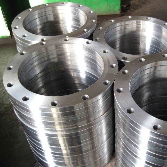
Suppliers of ASME B16.47 Series A Welding Neck Flange, Lap joint Flanges, ASME B16.47 Series B Class 300 Flanges, Check Sizes And Dimensions Of ASME B16.47 Series B Forged Flanges, Ready Stock of ASME B16.47 Socket Weld Flange, ANSI B16.47 Series A Class 150 Flanges.
ASME B16.47 Flange Specifications
Size Range
1/2" (15 NB) to 48" (1200NB) DN10~DN5000
Class / Pressure Rating
150#, 300#, 600#, 900#, 1500#, 2500#, PN6, PN10, PN16, PN25, PN40, PN64 etc.
Standards / Dimensions
ANSI/ASME B16.5, B16.47 Series A & B, B16.48, BS4504, BS 10, EN-1092, DIN, BS, GOST, MSS SP-44, ISO70051, JISB2220, BS1560-3.1, API7S-15, API7S-43, API605
Connection Type
Ring Joint Flange (RTJ), Flat Face Flange (FF), Raised Face Flange (RF), Male and Female Flange (M & F), Lap Joint Flange, Large and Small Tongue-and-Groove Flange (T & G)
Find the largest ready stock of ASME B16.47 Series A Flanges, ASME B16.47 Slip On Flanges Dealer, ASME B16.47 Series A Flange Price List, Check Availability of B16.47 Threaded Flanges, ASME B16.47 Reducing Flanges Stockist, ASME B16.47 Series B BLRF Flanges Supplier, ASME B16.47 Forged Flanges in Mumbai, India.
ASME B16.47 Flanges Dimensions
| Series A Flanges Dimensions | Series B Flanges Dimensions |
| ASME B16.47 Series A Flanges Class 150 | ASME B16.47 Series B Flanges Class 75 |
| ASME B16.47 Series A Flanges Class 300 | ASME B16.47 Series B Flanges Class 150 |
| ASME B16.47 Series A Flanges Class 400 | ASME B16.47 Series B Flanges Class 300 |
| ASME B16.47 Series A Flanges Class 600 | ASME B16.47 Series B Flanges Class 400 |
| ASME B16.47 Series A Flanges Class 900 | ASME B16.47 Series B Flanges Class 600 |
| ASME B16.47 Series B Flanges Class 900 |
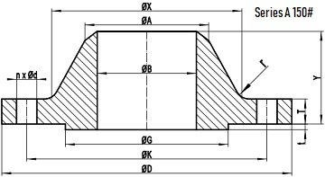
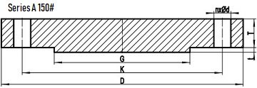
| NPS | D | K | G | X |
|---|---|---|---|---|
| 26″ | 870 | 806.4 | 749 | 676 |
| 28″ | 925 | 863.6 | 800 | 727 |
| 30″ | 985 | 914.4 | 857 | 781 |
| 32″ | 1060 | 977.9 | 914 | 832 |
| 34″ | 1110 | 1028.7 | 965 | 883 |
| 36″ | 1170 | 1085.8 | 1022 | 933 |
| 38″ | 1240 | 1149.4 | 1073 | 991 |
| 40″ | 1290 | 1200.2 | 1124 | 1041 |
| 42″ | 1345 | 1257.3 | 1194 | 1092 |
| 44″ | 1405 | 1314.4 | 1245 | 1143 |
| 46″ | 1455 | 1365.2 | 1295 | 1197 |
| 48″ | 1510 | 1422.4 | 1359 | 1248 |
| 50″ | 1570 | 1479.6 | 1410 | 1302 |
| 52″ | 1625 | 1536.7 | 1461 | 1353 |
| 54″ | 1685 | 1593.8 | 1511 | 1403 |
| 56″ | 1745 | 1651.0 | 1575 | 1457 |
| 58″ | 1805 | 1708.2 | 1626 | 1508 |
| 60″ | 1855 | 1759.0 | 1676 | 1559 |
- All dimensions are in MM.
- D: outside diameter of flange.
- K: diameter of bolt circle.
- G: diameter of raised face.
- X: diameter of hub of flange.
| NPS | A | TBL | TWN | Y |
|---|---|---|---|---|
| 26″ | 660.4 | 66.7 | 66.7 | 119 |
| 28″ | 711.2 | 69.9 | 69.9 | 124 |
| 30″ | 762.0 | 73.1 | 73.1 | 135 |
| 32″ | 812.8 | 79.4 | 79.4 | 143 |
| 34″ | 863.6 | 81.0 | 81.0 | 148 |
| 36″ | 914.4 | 88.9 | 88.9 | 156 |
| 38″ | 965.2 | 85.8 | 85.8 | 156 |
| 40″ | 1016.0 | 88.9 | 88.9 | 162 |
| 42″ | 1066.8 | 95.3 | 95.3 | 170 |
| 44″ | 1117.6 | 100.1 | 100.1 | 176 |
| 46″ | 1168.4 | 101.6 | 101.6 | 184 |
| 48″ | 1219.2 | 106.4 | 106.4 | 191 |
| 50″ | 1270.0 | 109.6 | 109.6 | 202 |
| 52″ | 1320.8 | 114.3 | 114.3 | 208 |
| 54″ | 1371.6 | 119.1 | 119.1 | 214 |
| 56″ | 1422.4 | 122.3 | 122.3 | 227 |
| 58″ | 1473.2 | 127.0 | 127.0 | 233 |
| 60″ | 1524.0 | 130.2 | 130.2 | 238 |
- All dimensions are in MM.
- A: Diameter of hub top of WN.
- TBL: minimum thickness of blind flange.
- TWN: minimum thickness of WN flange.
- Y: length through hub of WN.
- t: 2mm height of RF for Class 150 Series A flange.
| NPS | n | d | l | r |
|---|---|---|---|---|
| 26″ | 24 | 1-3/8 | 1-1/4 | 10 |
| 28″ | 28 | 1-3/8 | 1-1/4 | 11 |
| 30″ | 28 | 1-3/8 | 1-1/4 | 11 |
| 32″ | 28 | 1-5/8 | 1-1/2 | 11 |
| 34″ | 32 | 1-5/8 | 1-1/2 | 13 |
| 36″ | 32 | 1-5/8 | 1-1/2 | 13 |
| 38″ | 32 | 1-5/8 | 1-1/2 | 13 |
| 40″ | 36 | 1-5/8 | 1-1/2 | 13 |
| 42″ | 36 | 1-5/8 | 1-1/2 | 13 |
| 44″ | 40 | 1-5/8 | 1-1/2 | 13 |
| 46″ | 40 | 1-5/8 | 1-1/2 | 13 |
| 48″ | 44 | 1-5/8 | 1-1/2 | 13 |
| 50″ | 44 | 1-7/8 | 1-3/4 | 13 |
| 52″ | 44 | 1-7/8 | 1-3/4 | 13 |
| 54″ | 44 | 1-7/8 | 1-3/4 | 13 |
| 56″ | 48 | 1-7/8 | 1-3/4 | 13 |
| 58″ | 48 | 1-7/8 | 1-3/4 | 13 |
| 60″ | 52 | 1-7/8 | 1-3/4 | 13 |
- n: number of bolt holes.
- d: diameter of bolt hole.
- l: diameter of bolt.
- r: minimum fillet radius for WN.
- d and l are in inch units, while r is in mm unit.
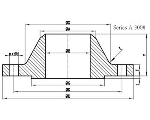
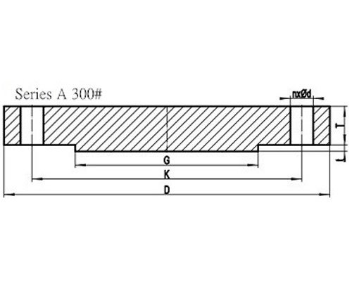
| NPS | D | K | G | X |
|---|---|---|---|---|
| 26″ | 970 | 876.3 | 749 | 721 |
| 28″ | 1035 | 939.8 | 800 | 775 |
| 30″ | 1090 | 997.0 | 857 | 827 |
| 32″ | 1150 | 1054.1 | 914 | 881 |
| 34″ | 1205 | 1104.9 | 965 | 937 |
| 36″ | 1270 | 1168.4 | 1022 | 991 |
| 38″ | 1170 | 1092.2 | 1029 | 994 |
| 40″ | 1240 | 1155.7 | 1086 | 1048 |
| 42″ | 1290 | 1206.5 | 1137 | 1099 |
| 44″ | 1355 | 1263.6 | 1194 | 1149 |
| 46″ | 1415 | 1320.8 | 1245 | 1203 |
| 48″ | 1465 | 1371.6 | 1302 | 1254 |
| 50″ | 1530 | 1428.8 | 1359 | 1305 |
| 52″ | 1580 | 1479.6 | 1410 | 1356 |
| 54″ | 1660 | 1549.4 | 1467 | 1410 |
| 56″ | 1710 | 1600.2 | 1518 | 1464 |
| 58″ | 1760 | 1651.0 | 1575 | 1514 |
| 60″ | 1810 | 1701.8 | 1626 | 1565 |
- All dimensions are in MM.
- D: outside diameter of flange.
- K: diameter of bolt circle.
- G: diameter of raised face.
- X: diameter of hub of flange.
| NPS | A | TBL | TWN | Y |
|---|---|---|---|---|
| 26″ | 660.4 | 66.7 | 66.7 | 119 |
| 28″ | 711.2 | 69.9 | 69.9 | 124 |
| 30″ | 762.0 | 73.1 | 73.1 | 135 |
| 32″ | 812.8 | 79.4 | 79.4 | 143 |
| 34″ | 863.6 | 81.0 | 81.0 | 148 |
| 36″ | 914.4 | 88.9 | 88.9 | 156 |
| 38″ | 965.2 | 85.8 | 85.8 | 156 |
| 40″ | 1016.0 | 88.9 | 88.9 | 162 |
| 42″ | 1066.8 | 95.3 | 95.3 | 170 |
| 44″ | 1117.6 | 100.1 | 100.1 | 176 |
| 46″ | 1168.4 | 101.6 | 101.6 | 184 |
| 48″ | 1219.2 | 106.4 | 106.4 | 191 |
| 50″ | 1270.0 | 109.6 | 109.6 | 202 |
| 52″ | 1320.8 | 114.3 | 114.3 | 208 |
| 54″ | 1371.6 | 119.1 | 119.1 | 214 |
| 56″ | 1422.4 | 122.3 | 122.3 | 227 |
| 58″ | 1473.2 | 127.0 | 127.0 | 233 |
| 60″ | 1524.0 | 130.2 | 130.2 | 238 |
- All dimensions are in MM.
- D: outside diameter of flange.
- K: diameter of bolt circle.
- G: diameter of raised face.
- X: diameter of hub of flange.
| NPS | A | TBL | TWN | Y |
|---|---|---|---|---|
| 26″ | 660.4 | 82.6 | 77.8 | 183 |
| 28″ | 711.2 | 88.9 | 84.2 | 195 |
| 30″ | 762.0 | 93.7 | 90.5 | 208 |
| 32″ | 812.8 | 98.5 | 96.9 | 221 |
| 34″ | 863.6 | 103.2 | 100.1 | 230 |
| 36″ | 914.4 | 109.6 | 103.2 | 240 |
| 38″ | 965.2 | 106.4 | 106.4 | 179 |
| 40″ | 1016.0 | 112.8 | 112.8 | 192 |
| 42″ | 1066.8 | 117.5 | 117.5 | 198 |
| 44″ | 1117.6 | 122.3 | 122.3 | 205 |
| 46″ | 1168.4 | 127.0 | 127.0 | 214 |
| 48″ | 1219.2 | 131.8 | 131.8 | 222 |
| 50″ | 1270.0 | 138.2 | 138.2 | 230 |
| 52″ | 1320.8 | 142.9 | 142.9 | 237 |
| 54″ | 1371.6 | 150.9 | 150.9 | 251 |
| 56″ | 1422.4 | 152.4 | 152.4 | 259 |
| 58″ | 1473.2 | 157.2 | 157.2 | 265 |
| 60″ | 1524.0 | 162.0 | 162.0 | 271 |
- All dimensions are in MM.
- A: Diameter of hub top of WN.
- TBL: minimum thickness of blind flange.
- TWN: minimum thickness of WN flange.
- Y: length through hub of WN.
- t: 2mm height of RF for Class 300 Series A flange.
| NPS | n | d | l | r |
|---|---|---|---|---|
| 26″ | 28 | 1-3/4 | 1-5/8 | 10 |
| 28″ | 28 | 1-3/4 | 1-5/8 | 11 |
| 30″ | 28 | 1-7/8 | 1-3/4 | 11 |
| 32″ | 28 | 2 | 1-7/8 | 11 |
| 34″ | 28 | 2 | 1-7/8 | 13 |
| 36″ | 32 | 2-1/8 | 2 | 13 |
| 38″ | 32 | 1-5/8 | 1-1/2 | 13 |
| 40″ | 32 | 1-3/4 | 1-5/8 | 13 |
| 42″ | 32 | 1-3/4 | 1-5/8 | 13 |
| 44″ | 32 | 1-7/8 | 1-3/4 | 13 |
| 46″ | 28 | 2 | 1-7/8 | 13 |
| 48″ | 32 | 2 | 1-7/8 | 13 |
| 50″ | 32 | 2-1/8 | 2 | 13 |
| 52″ | 32 | 2-1/8 | 2 | 13 |
| 54″ | 28 | 2-3/8 | 2-1/4 | 13 |
| 56″ | 28 | 2-3/8 | 2-1/4 | 13 |
| 58″ | 32 | 2-3/8 | 2-1/4 | 13 |
| 60″ | 32 | 2-3/8 | 2-1/4 | 13 |
General Note:
- n: number of bolt holes.
- d: diameter of bolt hole.
- l: diameter of bolt.
- r: minimum fillet radius for WN.
- d and l are in inch units, while r is in mm unit.
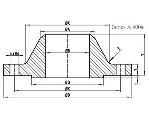
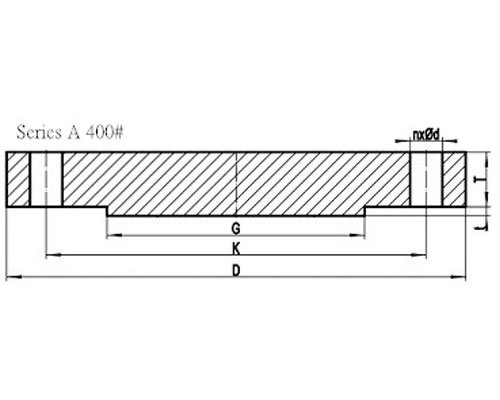
| NPS | D | K | G | X |
|---|---|---|---|---|
| 26″ | 970 | 876.3 | 749 | 727 |
| 28″ | 1035 | 939.8 | 800 | 783 |
| 30″ | 1090 | 997.0 | 857 | 837 |
| 32″ | 1150 | 1054.1 | 914 | 889 |
| 34″ | 1205 | 1104.9 | 965 | 945 |
| 36″ | 1270 | 1168.4 | 1022 | 1000 |
| 38″ | 1205 | 1117.6 | 1035 | 1003 |
| 40″ | 1270 | 1174.6 | 1092 | 1054 |
| 42″ | 1320 | 1225.6 | 1143 | 1108 |
| 44″ | 1385 | 1282.7 | 1200 | 1159 |
| 46″ | 1440 | 1339.8 | 1257 | 1213 |
| 48″ | 1510 | 1403.4 | 1308 | 1267 |
| 50″ | 1570 | 1460.5 | 1362 | 1321 |
| 52″ | 1620 | 1511.3 | 1413 | 1372 |
| 54″ | 1700 | 1581.2 | 1470 | 1426 |
| 56″ | 1755 | 1632.0 | 1527 | 1480 |
| 58″ | 1805 | 1682.8 | 1578 | 1530 |
| 60″ | 1885 | 1752.6 | 1635 | 1584 |
General Note:
- All dimensions are in MM.
- D: outside diameter of flange.
- K: diameter of bolt circle.
- G: diameter of raised face.
- X: diameter of hub of flange.
| NPS | A | TBL | TWN | Y |
|---|---|---|---|---|
| 26″ | 660.4 | 98.5 | 88.9 | 194 |
| 28″ | 711.2 | 104.8 | 95.3 | 206 |
| 30″ | 762.0 | 111.2 | 101.6 | 219 |
| 32″ | 812.8 | 115.9 | 108.0 | 232 |
| 34″ | 863.6 | 122.3 | 111.2 | 241 |
| 36″ | 914.4 | 128.6 | 114.3 | 251 |
| 38″ | 965.2 | 123.9 | 123.9 | 206 |
| 40″ | 1016.0 | 130.2 | 130.2 | 216 |
| 42″ | 1066.8 | 133.4 | 133.4 | 224 |
| 44″ | 1117.6 | 139.7 | 139.7 | 233 |
| 46″ | 1168.4 | 146.1 | 146.1 | 244 |
| 48″ | 1219.2 | 152.4 | 152.4 | 257 |
| 50″ | 1270.0 | 158.8 | 157.2 | 268 |
| 52″ | 1320.8 | 163.6 | 162.0 | 276 |
| 54″ | 1371.6 | 171.5 | 169.9 | 289 |
| 56″ | 1422.4 | 176.3 | 174.7 | 298 |
| 58″ | 1473.2 | 181.0 | 177.8 | 306 |
| 60″ | 1524.0 | 189.0 | 185.8 | 319 |
General Note:
- All dimensions are in MM.
- A: Diameter of hub top of WN.
- TBL: minimum thickness of blind flange.
- TWN: minimum thickness of WN flange.
- Y: length through hub of WN.
- t: 7mm height of RF for Class 400 Series A flange.
| NPS | n | d | l | r |
|---|---|---|---|---|
| 26″ | 28 | 1-7/8 | 1-3/4 | 11 |
| 28″ | 28 | 2 | 1-7/8 | 13 |
| 30″ | 28 | 2-1/8 | 2 | 13 |
| 32″ | 28 | 2-1/8 | 2 | 13 |
| 34″ | 28 | 2-1/8 | 2 | 14 |
| 36″ | 32 | 2-1/8 | 2 | 14 |
| 38″ | 32 | 1-7/8 | 1-3/4 | 14 |
| 40″ | 32 | 2 | 1-7/8 | 14 |
| 42″ | 32 | 2 | 1-7/8 | 14 |
| 44″ | 32 | 2-1/8 | 2 | 14 |
| 46″ | 36 | 2-1/8 | 2 | 14 |
| 48″ | 28 | 2-3/8 | 2-1/4 | 14 |
| 50″ | 32 | 2-3/8 | 2-1/4 | 14 |
| 52″ | 32 | 2-3/8 | 2-1/4 | 14 |
| 54″ | 28 | 2-5/8 | 2-1/2 | 14 |
| 56″ | 32 | 2-5/8 | 2-1/2 | 14 |
| 58″ | 32 | 2-5/8 | 2-1/2 | 14 |
| 60″ | 32 | 2-7/8 | 2-3/4 | 14 |
General Note:
- n: number of bolt holes.
- d: diameter of bolt hole.
- l: diameter of bolt.
- r: minimum fillet radius for WN.
- d and l are in inch units, while r is in mm unit.
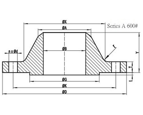
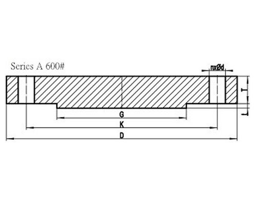
| NPS | D | K | G | X |
|---|---|---|---|---|
| 26″ | 1015 | 914.4 | 749 | 748 |
| 28″ | 1075 | 965.2 | 800 | 803 |
| 30″ | 1130 | 1022.4 | 857 | 862 |
| 32″ | 1195 | 1079.5 | 914 | 918 |
| 34″ | 1245 | 1130.3 | 965 | 973 |
| 36″ | 1315 | 1193.8 | 1022 | 1032 |
| 38″ | 1270 | 1162.0 | 1054 | 1022 |
| 40″ | 1320 | 1212.8 | 1111 | 1073 |
| 42″ | 1405 | 1282.7 | 1168 | 1127 |
| 44″ | 1455 | 1333.5 | 1226 | 1181 |
| 46″ | 1510 | 1390.6 | 1276 | 1235 |
| 48″ | 1595 | 1460.5 | 1334 | 1289 |
| 50″ | 1670 | 1524.0 | 1384 | 1343 |
| 52″ | 1720 | 1574.8 | 1435 | 1394 |
| 54″ | 1780 | 1632.0 | 1492 | 1448 |
| 56″ | 1855 | 1695.4 | 1543 | 1502 |
| 58″ | 1905 | 1746.2 | 1600 | 1553 |
| 60″ | 1995 | 1822.4 | 1657 | 1610 |
General Note:
- All dimensions are in MM.
- D: outside diameter of flange.
- K: diameter of bolt circle.
- G: diameter of raised face.
- X: diameter of hub of flange.
| NPS | A | TBL | TWN | Y |
|---|---|---|---|---|
| 26″ | 660.4 | 125.5 | 108.0 | 222 |
| 28″ | 711.2 | 131.8 | 111.2 | 235 |
| 30″ | 762.0 | 139.7 | 114.3 | 248 |
| 32″ | 812.8 | 147.7 | 117.5 | 260 |
| 34″ | 863.6 | 154.0 | 120.7 | 270 |
| 36″ | 914.4 | 162.0 | 123.9 | 283 |
| 38″ | 965.2 | 155.0 | 152.4 | 254 |
| 40″ | 1016.0 | 162.0 | 158.8 | 264 |
| 42″ | 1066.8 | 171.5 | 168.3 | 279 |
| 44″ | 1117.6 | 177.8 | 173.1 | 289 |
| 46″ | 1168.4 | 185.8 | 179.4 | 300 |
| 48″ | 1219.2 | 195.3 | 189.0 | 316 |
| 50″ | 1270.0 | 203.2 | 195.9 | 329 |
| 52″ | 1320.8 | 209.6 | 203.2 | 337 |
| 54″ | 1371.6 | 217.5 | 209.6 | 349 |
| 56″ | 1422.4 | 225.5 | 217.5 | 362 |
| 58″ | 1473.2 | 231.8 | 222.3 | 370 |
| 60″ | 1524.0 | 242.9 | 233.4 | 389 |
General Note:
- All dimensions are in MM.
- A: Diameter of hub top of WN.
- TBL: minimum thickness of blind flange.
- TWN: minimum thickness of WN flange.
- Y: length through hub of WN.
- t: 7mm height of RF for Class 600 Series A flange.
| NPS | n | d | l | r |
|---|---|---|---|---|
| 26″ | 28 | 2 | 1-7/8 | 13 |
| 28″ | 28 | 2-1/8 | 2 | 13 |
| 30″ | 28 | 2-1/8 | 2 | 13 |
| 32″ | 28 | 2-3/8 | 2-1/4 | 13 |
| 34″ | 28 | 2-3/8 | 2-1/4 | 14 |
| 36″ | 28 | 2-5/8 | 2-1/2 | 14 |
| 38″ | 28 | 2-3/8 | 2-1/4 | 14 |
| 40″ | 32 | 2-3/8 | 2-1/4 | 14 |
| 42″ | 28 | 2-5/8 | 2-1/2 | 14 |
| 44″ | 32 | 2-5/8 | 2-1/2 | 14 |
| 46″ | 32 | 2-5/8 | 2-1/2 | 14 |
| 48″ | 32 | 2-7/8 | 2-3/4 | 14 |
| 50″ | 28 | 3-1/8 | 3 | 14 |
| 52″ | 32 | 3-1/8 | 3 | 14 |
| 54″ | 32 | 3-1/8 | 3 | 14 |
| 56″ | 32 | 3-3/8 | 3-1/4 | 16 |
| 58″ | 32 | 3-3/8 | 3-1/4 | 16 |
| 60″ | 28 | 3-5/8 | 3-1/2 | 17 |
General Note:
- n: number of bolt holes.
- d: diameter of bolt hole.
- l: diameter of bolt.
- r: minimum fillet radius for WN.
- d and l are in inch units, while r is in mm unit.
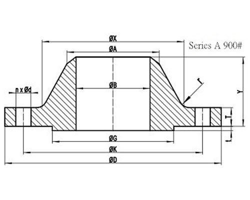
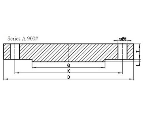
| NPS | D | K | G | X |
|---|---|---|---|---|
| 26″ | 1085 | 952.5 | 749 | 775 |
| 28″ | 1170 | 1022.4 | 800 | 832 |
| 30″ | 1230 | 1085.8 | 857 | 889 |
| 32″ | 1315 | 1155.7 | 914 | 946 |
| 34″ | 1395 | 1225.6 | 965 | 1006 |
| 36″ | 1460 | 1289.0 | 1022 | 1064 |
| 38″ | 1460 | 1289.0 | 1099 | 1073 |
| 40″ | 1510 | 1339.8 | 1162 | 1127 |
| 42″ | 1560 | 1390.6 | 1213 | 1176 |
| 44″ | 1650 | 1463.7 | 1270 | 1235 |
| 46″ | 1735 | 1536.7 | 1334 | 1292 |
| 48″ | 1785 | 1587.5 | 1384 | 1343 |
| 50″ | – | – | – | – |
| 52″ | – | – | – | – |
| 54″ | – | – | – | – |
| 56″ | – | – | – | – |
| 58″ | – | – | – | – |
| 60″ | – | – | – | – |
General Note:
- All dimensions are in MM.
- D: outside diameter of flange.
- K: diameter of bolt circle.
- G: diameter of raised face.
- X: diameter of hub of flange.
| NPS | A | TBL | TWN | Y |
|---|---|---|---|---|
| 26″ | 660.4 | 160.4 | 139.7 | 286 |
| 28″ | 711.2 | 171.5 | 142.9 | 298 |
| 30″ | 762.0 | 182.6 | 149.3 | 311 |
| 32″ | 812.8 | 193.7 | 158.8 | 330 |
| 34″ | 863.6 | 204.8 | 165.1 | 349 |
| 36″ | 914.4 | 214.4 | 171.5 | 362 |
| 38″ | 965.2 | 215.9 | 190.5 | 352 |
| 40″ | 1016.0 | 223.9 | 196.9 | 364 |
| 42″ | 1066.8 | 231.8 | 206.4 | 371 |
| 44″ | 1117.6 | 242.9 | 214.4 | 391 |
| 46″ | 1168.4 | 255.6 | 225.5 | 411 |
| 48″ | 1219.2 | 263.6 | 233.4 | 419 |
| 50″ | – | – | – | – |
| 52″ | – | – | – | – |
| 54″ | – | – | – | – |
| 56″ | – | – | – | – |
| 58″ | – | – | – | – |
| 60″ | – | – | – | – |
General Note:
- All dimensions are in MM.
- A: Diameter of hub top of WN.
- TBL: minimum thickness of blind flange.
- TWN: minimum thickness of WN flange.
- Y: length through hub of WN.
- t: 7mm height of RF for Class 900 Series A flange.
| NPS | n | d | l | r |
|---|---|---|---|---|
| 26″ | 20 | 2-7/8 | 2-3/4 | 11 |
| 28″ | 20 | 3-1/8 | 3 | 13 |
| 30″ | 20 | 3-1/8 | 3 | 13 |
| 32″ | 20 | 3-3/8 | 3-1/4 | 13 |
| 34″ | 20 | 3-5/8 | 3-1/2 | 14 |
| 36″ | 20 | 3-5/8 | 3-1/2 | 14 |
| 38″ | 20 | 3-5/8 | 3-1/2 | 19 |
| 40″ | 24 | 3-5/8 | 3-1/2 | 21 |
| 42″ | 24 | 3-5/8 | 3-1/2 | 21 |
| 44″ | 24 | 3-7/8 | 3-3/4 | 22 |
| 46″ | 24 | 4-1/8 | 4 | 22 |
| 48″ | 24 | 4-1/8 | 4 | 24 |
| 50″ | – | – | – | – |
| 52″ | – | – | – | – |
| 54″ | – | – | – | – |
| 56″ | – | – | – | – |
| 58″ | – | – | – | – |
| 60″ | – | – | – | – |
General Note:
- n: number of bolt holes.
- d: diameter of bolt hole.
- l: diameter of bolt.
- r: minimum fillet radius for WN.
- d and l are in inch units, while r is in mm unit.

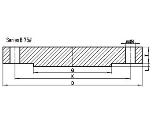
| NPS | D | K | G | X |
|---|---|---|---|---|
| 26 | 760 | 723.9 | 705 | 676 |
| 28 | 815 | 774.7 | 756 | 727 |
| 30 | 865 | 825.5 | 806 | 778 |
| 32 | 915 | 876.3 | 857 | 829 |
| 34 | 965 | 927.1 | 908 | 879 |
| 36 | 1035 | 992.2 | 965 | 935 |
| 38 | 1085 | 1043.0 | 1016 | 986 |
| 40 | 1135 | 1093.8 | 1067 | 1037 |
| 42 | 1185 | 1144.6 | 1118 | 1087 |
| 44 | 1250 | 1203.3 | 1175 | 1140 |
| 46 | 1300 | 1254.1 | 1226 | 1191 |
| 48 | 1355 | 1304.9 | 1276 | 1241 |
| 50 | 1405 | 1355.7 | 1327 | 1294 |
| 52 | 1455 | 1409.7 | 1378 | 1345 |
| 54 | 1510 | 1460.5 | 1429 | 1397 |
| 56 | 1575 | 1520.8 | 1486 | 1451 |
| 58 | 1625 | 1571.6 | 1537 | 1502 |
| 60 | 1675 | 1622.4 | 1588 | 1553 |
General Note:
- All dimensions are in MM.
- D: outside diameter of flange.
- K: diameter of bolt circle.
- G: diameter of raised face.
- X: diameter of hub of WN flange.
| NPS | A | TBL | TWN | Y |
|---|---|---|---|---|
| 26 | 661.9 | 31.9 | 31.9 | 57 |
| 28 | 712.7 | 31.9 | 31.9 | 60 |
| 30 | 763.5 | 31.9 | 31.9 | 64 |
| 32 | 814.3 | 35.0 | 33.5 | 68 |
| 34 | 865.1 | 36.6 | 33.5 | 72 |
| 36 | 915.9 | 40.9 | 35.0 | 84 |
| 38 | 966.7 | 43.0 | 36.6 | 87 |
| 40 | 1017.5 | 43.0 | 36.6 | 91 |
| 42 | 1068.3 | 46.3 | 38.2 | 94 |
| 44 | 1119.1 | 47.7 | 41.4 | 103 |
| 46 | 1169.9 | 49.3 | 43.0 | 106 |
| 48 | 1220.7 | 52.5 | 44.6 | 110 |
| 50 | 1271.5 | 54.1 | 46.2 | 114 |
| 52 | 1322.3 | 55.7 | 46.2 | 119 |
| 54 | 1373.1 | 58.9 | 47.8 | 124 |
| 56 | 1423.9 | 60.4 | 49.3 | 133 |
| 58 | 1474.7 | 62.0 | 50.9 | 137 |
| 60 | 1525.5 | 65.2 | 54.1 | 143 |
General Note:
- All dimensions are in MM.
- A: Diameter of hub top of WN.
- TBL: minimum thickness of blind flange.
- TWN: minimum thickness of WN flange.
- Y: length through hub of WN.
- t: 2mm height of RF for Class 75 Series B flange.
| NPS | n | d | l | r |
|---|---|---|---|---|
| 26 | 36 | 3/4 | 5/8 | 8 |
| 28 | 40 | 3/4 | 5/8 | 8 |
| 30 | 44 | 3/4 | 5/8 | 8 |
| 32 | 48 | 3/4 | 5/8 | 8 |
| 34 | 52 | 3/4 | 5/8 | 8 |
| 36 | 40 | 7/8 | 3/4 | 10 |
| 38 | 40 | 7/8 | 3/4 | 10 |
| 40 | 44 | 7/8 | 3/4 | 10 |
| 42 | 48 | 7/8 | 3/4 | 10 |
| 44 | 36 | 1 | 7/8 | 10 |
| 46 | 40 | 1 | 7/8 | 10 |
| 48 | 44 | 1 | 7/8 | 10 |
| 50 | 44 | 1 | 7/8 | 10 |
| 52 | 48 | 1 | 7/8 | 10 |
| 54 | 48 | 1 | 7/8 | 10 |
| 56 | 40 | 1-1/8 | 1 | 11 |
| 58 | 44 | 1-1/8 | 1 | 11 |
| 60 | 44 | 1-1/8 | 1 | 11 |
General Note:
- n: number of bolt holes.
- d: diameter of bolt hole.
- l: diameter of bolt.
- r: minimum fillet radius for WN.
- d and l are in inch units, while r is in mm unit.
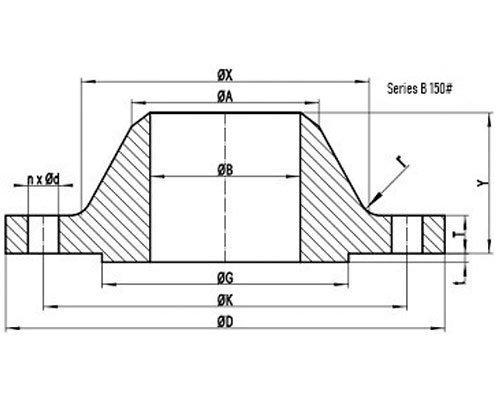
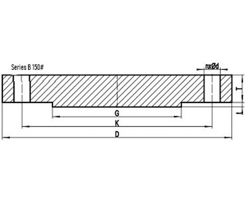
| NPS | D | K | G | X |
|---|---|---|---|---|
| 26 | 785 | 744.5 | 711 | 684 |
| 28 | 835 | 795.3 | 762 | 735 |
| 30 | 885 | 846.1 | 813 | 787 |
| 32 | 940 | 900.1 | 864 | 840 |
| 34 | 1005 | 957.3 | 921 | 892 |
| 36 | 1055 | 1009.6 | 972 | 945 |
| 38 | 1125 | 1070.0 | 1022 | 997 |
| 40 | 1175 | 1120.8 | 1080 | 1049 |
| 42 | 1225 | 1171.6 | 1130 | 1102 |
| 44 | 1275 | 1222.4 | 1181 | 1153 |
| 46 | 1340 | 1284.3 | 1235 | 1205 |
| 48 | 1390 | 1335.1 | 1289 | 1257 |
| 50 | 1445 | 1385.9 | 1340 | 1308 |
| 52 | 1495 | 1436.7 | 1391 | 1360 |
| 54 | 1550 | 1492.2 | 1441 | 1413 |
| 56 | 1600 | 1543.0 | 1492 | 1465 |
| 58 | 1675 | 1611.3 | 1543 | 1516 |
| 60 | 1725 | 1662.1 | 1600 | 1570 |
General Note:
- All dimensions are in MM.
- D: outside diameter of flange.
- K: diameter of bolt circle.
- G: outside diameter of raised face.
- X: diameter of hub of WN flange.
| NPS | A | TBL | TWN | Y |
|---|---|---|---|---|
| 26 | 661.9 | 43.0 | 39.8 | 87 |
| 28 | 712.7 | 46.2 | 43.0 | 94 |
| 30 | 763.5 | 49.3 | 43.0 | 98 |
| 32 | 814.3 | 52.5 | 44.6 | 106 |
| 34 | 865.1 | 55.7 | 47.7 | 109 |
| 36 | 915.9 | 57.3 | 50.9 | 116 |
| 38 | 968.2 | 62.0 | 52.5 | 122 |
| 40 | 1019.0 | 65.2 | 54.1 | 127 |
| 42 | 1069.8 | 66.8 | 57.3 | 132 |
| 44 | 1120.6 | 70.0 | 58.9 | 135 |
| 46 | 1171.4 | 73.1 | 60.4 | 143 |
| 48 | 1222.2 | 76.3 | 63.6 | 148 |
| 50 | 1273.0 | 79.5 | 66.8 | 152 |
| 52 | 1323.8 | 82.7 | 68.4 | 156 |
| 54 | 1374.6 | 85.8 | 70.0 | 160 |
| 56 | 1425.4 | 89.0 | 71.6 | 165 |
| 58 | 1476.2 | 91.9 | 73.1 | 173 |
| 60 | 1527.0 | 95.4 | 74.7 | 178 |
General Note:
- All dimensions are in MM.
- A: Diameter of hub top of WN.
- TBL: minimum thickness of blind flange.
- TWN: minimum thickness of WN flange.
- Y: length through hub of WN.
- t: 2mm height of RF for Class 150 Series B flange.
| NPS | n | d | l | r |
|---|---|---|---|---|
| 26 | 36 | 7/8 | 3/4 | 10 |
| 28 | 40 | 7/8 | 3/4 | 10 |
| 30 | 44 | 7/8 | 3/4 | 10 |
| 32 | 48 | 7/8 | 3/4 | 10 |
| 34 | 40 | 1 | 7/8 | 10 |
| 36 | 44 | 1 | 7/8 | 10 |
| 38 | 40 | 1-1/8 | 1 | 10 |
| 40 | 44 | 1-1/8 | 1 | 10 |
| 42 | 48 | 1-1/8 | 1 | 11 |
| 44 | 52 | 1-1/8 | 1 | 11 |
| 46 | 40 | 1-1/4 | 1-1/8 | 11 |
| 48 | 44 | 1-1/4 | 1-1/8 | 11 |
| 50 | 48 | 1-1/4 | 1-1/8 | 11 |
| 52 | 52 | 1-1/4 | 1-1/8 | 11 |
| 54 | 56 | 1-1/4 | 1-1/8 | 11 |
| 56 | 60 | 1-1/4 | 1-1/8 | 14 |
| 58 | 48 | 1-3/8 | 1-1/4 | 14 |
| 60 | 52 | 1-3/8 | 1-1/4 | 14 |
General Note:
- n: number of bolt holes.
- d: diameter of bolt hole.
- l: diameter of bolt.
- r: minimum fillet radius for WN.
- d and l are in inch units, while r is in mm unit.
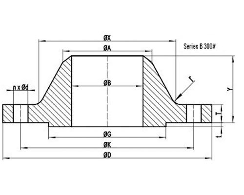

| NPS | D | K | G | X |
|---|---|---|---|---|
| 26 | 865 | 803.3 | 737 | 702 |
| 28 | 920 | 857.2 | 787 | 756 |
| 30 | 990 | 920.8 | 845 | 813 |
| 32 | 1055 | 977.9 | 902 | 864 |
| 34 | 1110 | 1031.9 | 953 | 918 |
| 36 | 1170 | 1089.0 | 1010 | 965 |
| 38 | 1220 | 1139.8 | 1060 | 1016 |
| 40 | 1275 | 1190.6 | 1114 | 1067 |
| 42 | 1335 | 1244.6 | 1168 | 1118 |
| 44 | 1385 | 1295.4 | 1219 | 1173 |
| 46 | 1460 | 1365.2 | 1270 | 1229 |
| 48 | 1510 | 1416.0 | 1327 | 1278 |
| 50 | 1560 | 1466.8 | 1378 | 1330 |
| 52 | 1615 | 1517.6 | 1429 | 1383 |
| 54 | 1675 | 1578.0 | 1480 | 1435 |
| 56 | 1765 | 1651.0 | 1537 | 1494 |
| 58 | 1825 | 1712.9 | 1594 | 1548 |
| 60 | 1880 | 1763.7 | 1651 | 1599 |
General Note:
- All dimensions are in MM.
- D: outside diameter of flange.
- K: diameter of bolt circle.
- G: outside diameter of raised face.
- X: diameter of hub of WN flange.
| NPS | A | TBL | TWN | Y |
|---|---|---|---|---|
| 26 | 665.2 | 87.4 | 87.7 | 143 |
| 28 | 716.0 | 87.4 | 87.4 | 148 |
| 30 | 768.4 | 92.1 | 92.1 | 156 |
| 32 | 819.2 | 101.6 | 101.6 | 167 |
| 34 | 870.0 | 101.6 | 101.6 | 171 |
| 36 | 920.8 | 101.6 | 101.6 | 179 |
| 38 | 971.6 | 109.6 | 109.6 | 191 |
| 40 | 1022.4 | 114.3 | 114.3 | 197 |
| 42 | 1074.7 | 117.5 | 117.5 | 203 |
| 44 | 1125.5 | 125.5 | 125.5 | 213 |
| 46 | 1176.3 | 128.6 | 127.0 | 221 |
| 48 | 1227.1 | 133.4 | 127.0 | 222 |
| 50 | 1277.9 | 138.2 | 136.6 | 233 |
| 52 | 1328.7 | 142.6 | 141.3 | 241 |
| 54 | 1379.5 | 147.7 | 135.0 | 238 |
| 56 | 1430.3 | 155.4 | 152.4 | 267 |
| 58 | 1481.1 | 160.4 | 152.4 | 273 |
| 60 | 1531.9 | 165.1 | 149.3 | 270 |
General Note:
- All dimensions are in MM.
- A: Diameter of hub top of WN.
- TBL: minimum thickness of blind flange.
- TWN: minimum thickness of WN flange.
- Y: length through hub of WN.
- t: 2mm height of RF for Class 300 Series B flange.
| NPS | n | d | l | r |
|---|---|---|---|---|
| 26 | 32 | 1-3/8 | 1-1/4 | 14 |
| 28 | 36 | 1-3/8 | 1-1/4 | 14 |
| 30 | 36 | 1-1/2 | 1-3/8 | 14 |
| 32 | 32 | 1-5/8 | 1-1/2 | 16 |
| 34 | 36 | 1-5/8 | 1-1/2 | 16 |
| 36 | 32 | 1-3/4 | 1-5/8 | 16 |
| 38 | 36 | 1-3/4 | 1-5/8 | 16 |
| 40 | 40 | 1-3/4 | 1-5/8 | 16 |
| 42 | 36 | 1-7/8 | 1-3/4 | 16 |
| 44 | 40 | 1-7/8 | 1-3/4 | 16 |
| 46 | 36 | 2 | 1-7/8 | 16 |
| 48 | 40 | 2 | 1-7/8 | 16 |
| 50 | 44 | 2 | 1-7/8 | 16 |
| 52 | 48 | 2 | 1-7/8 | 16 |
| 54 | 48 | 2 | 1-7/8 | 16 |
| 56 | 36 | 2-3/8 | 2-1/4 | 17 |
| 58 | 40 | 2-3/8 | 2-1/4 | 17 |
| 60 | 40 | 2-3/8 | 2-1/4 | 17 |
General Note:
- n: number of bolt holes.
- d: diameter of bolt hole.
- l: diameter of bolt.
- r: minimum fillet radius for WN.
- d and l are in inch units, while r is in mm unit.
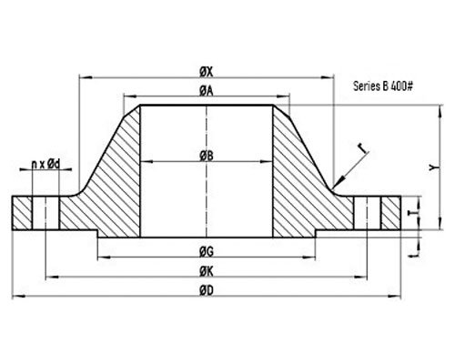
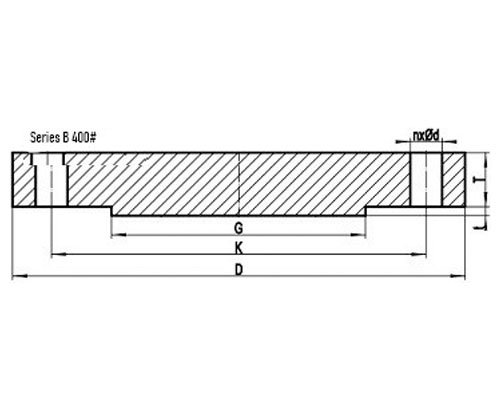
| NPS | D | K | G | X |
|---|---|---|---|---|
| 26 | 850 | 781.0 | 711 | 689 |
| 28 | 915 | 838.2 | 762 | 740 |
| 30 | 970 | 895.4 | 819 | 794 |
| 32 | 1035 | 952.5 | 873 | 845 |
| 34 | 1085 | 1003.3 | 927 | 899 |
| 36 | 1155 | 1066.8 | 981 | 952 |
General Note:
- All dimensions are in MM.
- D: outside diameter of flange.
- K: diameter of bolt circle.
- G: outside diameter of raised face.
- X: diameter of hub of WN flange.
| NPS | A | TBL | TWN | Y |
|---|---|---|---|---|
| 26 | 660.4 | 88.9 | 88.9 | 149 |
| 28 | 711.2 | 95.3 | 95.3 | 159 |
| 30 | 762.0 | 101.6 | 101.6 | 170 |
| 32 | 812.8 | 108.0 | 108.0 | 179 |
| 34 | 863.6 | 111.2 | 111.2 | 187 |
| 36 | 914.4 | 119.1 | 119.1 | 200 |
General Note:
- All dimensions are in MM.
- A: Diameter of hub top of WN.
- TBL: minimum thickness of blind flange.
- TWN: minimum thickness of WN flange.
- Y: length through hub of WN.
- t: 7mm height of RF for Class 400 Series B flange.
| NPS | n | d | l | r |
|---|---|---|---|---|
| 26 | 28 | 1-1/2 | 1-3/8 | 11 |
| 28 | 24 | 1-5/8 | 1-1/2 | 13 |
| 30 | 28 | 1-5/8 | 1-1/2 | 13 |
| 32 | 28 | 1-3/4 | 1-5/8 | 13 |
| 34 | 32 | 1-3/4 | 1-5/8 | 14 |
| 36 | 28 | 1-7/8 | 1-3/4 | 14 |
General Note:
- n: number of bolt holes.
- d: diameter of bolt hole.
- l: diameter of bolt.
- r: minimum fillet radius for WN.
- d and l are in inch units, while r is in mm unit.
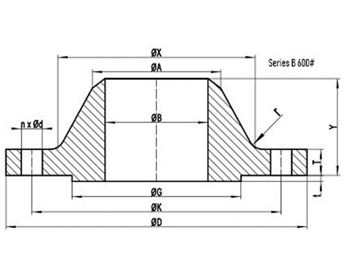
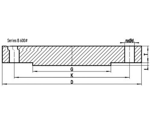
| NPS | D | K | G | X |
|---|---|---|---|---|
| 26 | 890 | 806.4 | 727 | 698 |
| 28 | 950 | 863.6 | 784 | 752 |
| 30 | 1020 | 927.1 | 841 | 806 |
| 32 | 1085 | 984.2 | 895 | 860 |
| 34 | 1160 | 1054.1 | 953 | 914 |
| 36 | 1215 | 1104.9 | 1010 | 968 |
General Note:
- All dimensions are in MM.
- D: outside diameter of flange.
- K: diameter of bolt circle.
- G: outside diameter of raised face.
- X: diameter of hub of WN flange.
| NPS | A | TBL | TWN | Y |
|---|---|---|---|---|
| 26 | 660.4 | 111.3 | 111.2 | 181 |
| 28 | 711.2 | 115.9 | 115.9 | 190 |
| 30 | 762.0 | 127.0 | 125.5 | 205 |
| 32 | 812.8 | 134.9 | 130.2 | 216 |
| 34 | 863.6 | 144.2 | 141.3 | 233 |
| 36 | 914.4 | 150.9 | 146.1 | 243 |
General Note:
- All dimensions are in MM.
- A: Diameter of hub top of WN.
- TBL: minimum thickness of blind flange.
- TWN: minimum thickness of WN flange.
- Y: length through hub of WN.
- t: 7mm height of RF for Class 600 Series B flange.
| NPS | n | d | l | r |
|---|---|---|---|---|
| 26 | 28 | 1-3/4 | 1-5/8 | 13 |
| 28 | 28 | 1-7/8 | 1-3/4 | 13 |
| 30 | 28 | 2 | 1-7/8 | 13 |
| 32 | 28 | 2-1/8 | 2 | 13 |
| 34 | 24 | 2-3/8 | 2-1/4 | 14 |
| 36 | 28 | 2-3/8 | 2-1/4 | 14 |
General Note:
- n: number of bolt holes.
- d: diameter of bolt hole.
- l: diameter of bolt.
- r: minimum fillet radius for WN.
- d and l are in inch units, while r is in mm unit.
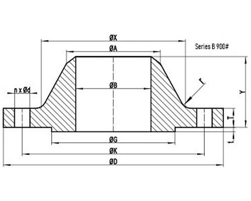
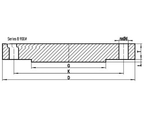
| NPS | D | K | G | X |
|---|---|---|---|---|
| 26 | 1020 | 901.7 | 762 | 743 |
| 28 | 1105 | 971.6 | 819 | 797 |
| 30 | 1180 | 1035.0 | 876 | 851 |
| 32 | 1240 | 1092.2 | 927 | 908 |
| 34 | 1315 | 1155.7 | 991 | 962 |
| 36 | 1345 | 1200.2 | 1029 | 1016 |
General Note:
- All dimensions are in MM.
- D: outside diameter of flange.
- K: diameter of bolt circle.
- G: outside diameter of raised face.
- X: diameter of hub of WN flange.
| NPS | A | TBL | TWN | Y |
|---|---|---|---|---|
| 26 | 660.4 | 154.0 | 135.0 | 259 |
| 28 | 711.2 | 166.7 | 147.7 | 276 |
| 30 | 762.0 | 176.1 | 155.6 | 289 |
| 32 | 812.8 | 186.0 | 160.4 | 303 |
| 34 | 863.6 | 195.0 | 171.5 | 319 |
| 36 | 914.4 | 201.7 | 173.1 | 325 |
General Note:
- All dimensions are in MM.
- A: Diameter of hub top of WN.
- TBL: minimum thickness of blind flange.
- TWN: minimum thickness of WN flange.
- Y: length through hub of WN.
- t: 7mm height of RF for Class 900 Series B flange.
| NPS | n | d | l | r |
|---|---|---|---|---|
| 26 | 20 | 2-5/8 | 2-1/2 | 11 |
| 28 | 20 | 2-7/8 | 2-3/4 | 13 |
| 30 | 20 | 3-1/8 | 3 | 13 |
| 32 | 20 | 3-1/8 | 3 | 13 |
| 34 | 20 | 3-3/8 | 3-1/4 | 14 |
| 36 | 24 | 3-1/8 | 3 | 14 |
General Note:
- n: number of bolt holes.
- d: diameter of bolt hole.
- l: diameter of bolt.
- r: minimum fillet radius for WN.
- d and l are in inch units, while r is in mm unit.
Find the largest ready stock of ASME B16.47 Series A Flanges, ASME B16.47 Slip On Flanges Dealer, ASME B16.47 Series A Flange Price List, Check Availability of B16.47 Threaded Flanges, ASME B16.47 Reducing Flanges Stockist, ASME B16.47 Series B BLRF Flanges Supplier, ASME B16.47 Forged Flanges in Mumbai, India.
ASME B16.47 Flanges Weight Chart
| Flange ASME B16.47-A (MSS SP 44) | ||||||||
| NPS SIZE | CLASS 150 | CLASS 300 | CLASS 600 | CLASS 900 | ||||
| WELDING NECK | BLIND | WELDING NECK | BLIND | WELDING NECK | BLIND | WELDING NECK | BLIND | |
| 22 | 109 | 162 | 204 | 284 | 310 | 437 | ||
| 26 | 154 | 321 | 291 | 477 | 450 | 777 | 890 | 1100 |
| 28 | 175 | 380 | 352 | 584 | 506 | 909 | 1055 | 1350 |
| 30 | 204 | 450 | 405 | 685 | 575 | 1074 | 1230 | 1610 |
| 32 | 254 | 560 | 465 | 793 | 642 | 1253 | 1480 | 1940 |
| 34 | 273 | 625 | 523 | 919 | 705 | 1427 | 1750 | 2310 |
| 36 | 321 | 760 | 580 | 1072 | 800 | 1665 | 1997 | 2660 |
| 38 | 358 | 830 | 324 | 900 | 674 | 1509 | 2000 | 2690 |
| 40 | 386 | 925 | 391 | 1066 | 725 | 1695 | 2161 | 2950 |
| 42 | 442 | 1080 | 428 | 1206 | 895 | 2028 | 2379 | 3280 |
| 44 | 491 | 1230 | 485 | 1378 | 951 | 2246 | 3321 | 3810 |
| 46 | 525 | 1345 | 559 | 1570 | 1055 | 2543 | 3224 | 4430 |
| 48 | 580 | 1520 | 597 | 1745 | 1247 | 2951 | 3500 | 4860 |
| 50 | 624 | 1668 | 674 | 1983 | 1423 | 3381 | ||
| 52 | 689 | 1867 | 728 | 2194 | 1493 | 3682 | ||
| 54 | 760 | 2088 | 871 | 2538 | 1637 | 4091 | ||
| 56 | 845 | 2308 | 921 | 2728 | 1843 | 4585 | ||
| 58 | 923 | 2554 | 968 | 2975 | 1954 | 4986 | ||
| 60 | 971 | 2765 | 1032 | 3250 | 2353 | 5750 | ||
| Flange ASME B16.47-B (API 605) | ||||||||
| NPS Size | CLASS 150 | CLASS 300 | CLASS 600 | CLASS 900 | ||||
| WELDING NECK | BLIND | WELDING NECK | BLIND | WELDING NECK | BLIND | WELDING NECK | BLIND | |
| 26 | 65 | 165 | 193 | 404 | 260 | 534 | ||
| 28 | 75 | 200 | 211 | 457 | 305 | 637 | ||
| 30 | 82 | 226 | 258 | 555 | 378 | 793 | ||
| 32 | 94 | 263 | 315 | 693 | 436 | 925 | ||
| 34 | 113 | 320 | 339 | 765 | 550 | 1150 | ||
| 36 | 128 | 374 | 380 | 858 | 591 | 1290 | ||
| 38 | 153 | 434 | 425 | 1005 | 668 | 1481 | ||
| 40 | 166 | 489 | 459 | 1132 | 718 | 1662 | ||
| 42 | 182 | 560 | 514 | 1280 | 888 | 1989 | ||
| 44 | 195 | 626 | 567 | 1466 | 942 | 2188 | ||
| 46 | 229 | 709 | 666 | 1657 | 1046 | 2458 | ||
| 48 | 248 | 799 | 687 | 1772 | 1237 | 2859 | ||
| 50 | 268 | 899 | 797 | 2029 | 1412 | 3280 | ||
| 52 | 284 | 985 | 806 | 2230 | 1481 | 3573 | ||
| 54 | 309 | 1081 | 840 | 2310 | 1623 | 3949 | ||
| 56 | 329 | 1181 | 1117 | 2891 | 1829 | 4423 | ||
| 58 | 391 | 1322 | 1194 | 3093 | 1939 | 4791 | ||
| 60 | 414 | 1430 | 1215 | 3213 | 2336 | 5533 | ||
ASME B16.47 Flanges Bore Chart
| Pipe Size | O.D. in inches |
5 | 10 | 20 | 30 | 40 | STD | 60 | 80 | XH | 100 | ||||
| 1/2 | 0.840 | .065 .710 |
.083 .674 |
.109 .622 |
.109 .622 |
.147 .546 |
.147 .546 |
.187 .466 |
.294 .252 |
||||||
| 3/4 | 1.050 | .065 .920 |
.083 .884 |
.113 .824 |
.113 .824 |
.154 .742 |
.154 .742 |
.218 .614 |
.308 .434 |
||||||
| 1 | 1.315 | .065 1.185 |
.109 1.097 |
.133 1.049 |
.133 1.049 |
.179 .957 |
.179 .957 |
.250 .815 |
.358 .599 |
||||||
| 1 1/4 | 1.660 | .065 1.530 |
.109 1.442 |
.140 1.380 |
.140 1.380 |
.191 1.278 |
.191 1.278 |
.250 1.160 |
.382 .896 |
||||||
| 1 1/2 | 1.900 | .065 1.770 |
.109 1.682 |
.145 1.610 |
.145 1.610 |
.200 1.500 |
.200 1.500 |
.281 1.338 |
.400 1.100 |
||||||
| 2 | 2.375 | .065 2.245 |
.109 2.157 |
.154 2.067 |
.154 2.067 |
.218 1.939 |
.218 1.939 |
.343 1.687 |
.436 1.503 |
||||||
| 2 1/2 | 2.875 | .083 2.709 |
.120 2.635 |
.203 2.469 |
.203 2.469 |
.276 2.323 |
.276 2.323 |
.375 2.125 |
.552 1.771 |
||||||
| 3 | 3.500 | .083 3.334 |
.120 3.260 |
.216 3.068 |
.216 3.068 |
.300 2.900 |
.300 2.900 |
.437 2.626 |
.600 2.300 |
||||||
| 3 1/2 | 4 | .083 3.834 |
.120 3.760 |
.226 3.548 |
.226 3.548 |
.318 3.364 |
.318 3.364 |
.636 2.728 |
|||||||
| 4 | 4.5 | .083 4.334 |
.120 4.260 |
.237 4.026 |
.237 4.026 |
.281 3.938 |
.337 3.826 |
.337 3.826 |
.437 3.626 |
.531 3.438 |
.674 3.152 |
||||
| 5 | 5.563 | .109 5.345 |
.134 5.295 |
.258 5.047 |
.258 5.047 |
.375 4.813 |
.375 4.813 |
.500 4.563 |
.625 4.313 |
.750 4.063 |
|||||
| 6 | 6.625 | .109 6.407 |
.134 6.357 |
.280 6.065 |
.280 6.065 |
.432 5.761 |
.432 5.761 |
.562 5.501 |
.718 5.189 |
.864 4.897 |
|||||
| 8 | 8.625 | .109 8.407 |
.148 8.329 |
.250 8.125 |
.277 8.071 |
.322 7.981 |
.322 7.981 |
.406 7.813 |
.500 7.625 |
.500 7.625 |
.593 7.439 |
.718 7.189 |
.812 7.001 |
.906 6.813 |
.875 6.875 |
| 10 | 10.75 | .134 10.482 |
.165 10.420 |
.250 10.250 |
.307 10.136 |
.365 10.020 |
.365 10.020 |
.500 9.750 |
.593 9.562 |
.500 9.750 |
.718 9.314 |
.843 9.064 |
1.000 8.750 |
1.125 8.500 |
|
| 12 | 12.75 | .156 12.420 |
.180 12.390 |
.250 12.250 |
.330 12.090 |
.406 11.938 |
.375 12.000 |
.562 11.626 |
.687 11.374 |
.500 11.750 |
.843 11.064 |
1.000 10.750 |
1.125 10.500 |
1.312 10.126 |
|
| 14 | 14.0 | .250 13.500 |
.312 13.376 |
.375 13.250 |
.437 13.124 |
.375 13.250 |
.593 12.812 |
.750 12.500 |
.500 13.000 |
.937 12.126 |
1.093 11.814 |
1.250 11.500 |
1.406 11.188 |
||
| 16 | 16.0 | .250 15.500 |
.312 15.376 |
.375 15.250 |
.500 15.000 |
.375 15.250 |
.656 14.688 |
.843 14.312 |
.500 15.000 |
1.031 13.938 |
1.218 13.564 |
1.437 13.126 |
1.593 12.814 |
||
| 18 | 18.0 | .250 17.500 |
.312 17.376 |
.437 17.124 |
.562 16.876 |
.375 17.250 |
.750 16.500 |
.937 16.124 |
.500 17.000 |
1.156 15.688 |
1.375 15.250 |
1.562 14.876 |
1.781 14.438 |
||
| 20 | 20.0 | .250 19.500 |
.375 19.250 |
.500 19.000 |
.593 18.812 |
.375 19.250 |
.812 18.376 |
1.031 17.938 |
.500 19.000 |
1.280 17.440 |
1.500 17.000 |
1.750 16.500 |
1.968 16.064 |
||
| 22 | 22.0 | .250 21.500 |
.375 21.250 |
.500 21.000 |
.375 21.250 |
.875 20.250 |
1.125 19.750 |
.500 21.000 |
1.375 19.250 |
1.625 18.750 |
1.875 18.250 |
2.125 17.750 |
|||
| 24 | 24.0 | .250 23.500 |
.375 23.250 |
.562 22.876 |
.687 22.624 |
.375 23.250 |
.968 22.064 |
1.218 21.562 |
.500 23.000 |
1.531 20.938 |
1.812 20.376 |
2.062 19.876 |
2.343 19.314 |
||
| 26 | 26.0 | .312 25.376 |
.500 25.000 |
.375 25.250 |
.500 25.000 |
||||||||||
| 28 | 28.0 | .312 27.376 |
.500 27.000 |
.625 26.750 |
.375 27.250 |
.500 27.000 |
|||||||||
| 30 | 30.0 | .312 29.376 |
.500 29.000 |
.625 28.750 |
.375 29.250 |
.500 29.000 |
|||||||||
| 32 | 32.0 | .312 31.376 |
.500 31.000 |
.625 30.750 |
.688 30.624 |
.375 31.250 |
.500 31.000 |
||||||||
| 34 | 34.0 | .344 33.312 |
.500 33.000 |
.625 32.750 |
.688 32.624 |
.375 33.250 |
.500 33.000 |
||||||||
| 36 | 36.0 | .312 35.376 |
.500 35.000 |
.625 34.750 |
.750 34.500 |
.375 35.250 |
.500 35.000 |
||||||||
| 42 | 42.0 | .375 41.250 |
.500 41.000 |
||||||||||||
| 48 | 48.0 | .375 47.250 |
.500 47.000 |
ASME B16.47 Flange Tolerance Chart
| OD | ±0.12″ | ±3.2mm | |
| The diameter of Flange Face | 0.06″ (1.66mm) raised face | ±0.08″ | ±2.0mm |
| 0.25″ (6.44mm) raised face | ±0.04″ | ||
| er ofThe diameter of the Hub at the Point of Welding | ±0.21″, -0.06″ | ±5.5mm, -1.6mm | |
| ID | ±0.12″, -0.06″ | ±3.2mm, -1.6mm | |
| Thk. | Up to 1.0″ Thickness | ±0.12″, -0.00″ | ±3.2mm, -0.00mm |
| 1.0″ to 2.0″ | ±0.19″, -0.00″ | ±4.8mm, -0.00mm | |
| 2.0″ to 3.0″ | ±0.31″, -0.00″ | ±7.9mm, -0.00mm | |
| Over 3.0′ Thickness | ±0.38″, -0.00″ | ±9.6mm, -0.00mm | |
| Bolts Drilling | Bolt Circle Diameter | ±0.06″ | ±1.6mm |
| Bolt Hole Spacing | ±0.03″ | ±0.8mm | |
| The eccentricity of the Bolt Circle and Facing vs. Bore | ±0.06″ | ±1.6mm | |
| Length Through Hub for Welding Neck Flanges | ±0.19″ | ±4.8mm |
Best quality ASME B16.47 Series A Flanges, ASME B16.47 Flanges Facing Type & Finish, B16.47 Plate Flange Flat Face, ASME B16.47 Square Flange, ASME B16.47 Flanges Price, ASME B16.47 Nipoflange, ASME B16.47 Series B RTJ Flange, View Specification Of ANSI B16.47 Orifice Flange, ASME B16.47 Class 300 Flanges Raised Face, ASME B16.47 Weldoflange, ASME B16.47 Groove Flange, ASME B16.47 Expander Flanges at Best Price.
ASME B16.47 Flanges Applications
-
-
 Petrochemical Industries
-
 Pharmaceutical Equipment
-
 Power Generation
-
 Heating Systems and Heat Exchanger
-
 Pulp and Paper Industry
-
 Mining Support
-
 Chemical Equipment
-
 Gas Processing
-
 Plumbing
-
 Nuclear Power Systems
-
 Condensers
-
 Sea Water Equipment
-
 Buildings and Bridges
-
 Industrial Water Lines
-
 Food Processing Industry
-
 Fire Protection Systems
-
 Off-Shore Oil Drilling Companies
-
Australia, Afghanistan, Algeria, Angola, Argentina, Armenia, Azerbaijan, Bahrain, Bangladesh, Benin,
Bhutan, Botswana, Brazil, Brunei, Burkina Faso, Cambodia, Cameroon, Canada, Central Africa Republic,
Chad, Chile, Colombia, Cuba, Cyprus, DRC, Djibouti, Egypt, Equatorial Guinea, Eritrea, Eswatini,
Ethiopia, Fiji, Finland, France, Georgia, Germany, Ghana, Greece, Hungary, Iceland, Indonesia, Iran,
Iraq, Ireland, Israel, Italy, Japan, Jordan, Kazakhstan, Kenya, Kuwait, Kyrgyzstan, Laos, Lebanon,
Lesotho, Liberia, Libya, Lithuania, Madagascar, Malawi, Malaysia, Maldives, Mali, Mexico, Morocco,
Mozambique, Mauritania, Myanmar, Namibia, Nepal, Netherlands, New Zealand, Nigeria, Norway, Oman,
Panama, Peru, Philippines, Poland, Portugal, Palestine, Qatar, Russia, Rwanda, Romania, Saudi Arabia,
Senegal, Sierra Leone, Singapore, Slovakia, Somalia, South Africa, South Korea, South Sudan, Spain,
Sri Lanka, Sweden, Switzerland, Syria, Taiwan, Tajikistan, Tanzania, Tasmania, Thailand, The Gambia,
Timor-Leste, Togo, Tunisia, Turkey, Turkiye, Turkmenistan, Uganda, Uzbekistan, United Arab Emirates (UAE),
United Kingdom (UK), United States (US), Venezuela, Vietnam, Yemen, Zambia, Zimbabwe
Abu Dhabi, Amsterdam, Abuja, Accra, Addis Ababa, Ahmedabad, Algiers, Amman, Ankara, Antananarivo,
Ashgabat, Asmara, Astana, Athens, Baghdad, Baku, Bamako, Bandar Seri Begawan, Bangkok, Bangui,
Banjul, Beirut, Bengaluru, Berlin, Bishkek, Bloemfontein, Bogotá, Bern, Brasília, Bratislava,
Bucharest, Budapest, Buenos Aires, Cairo, Canberra, Cape Town, Caracas, Chennai, Coimbatore, Dakar,
Damascus, Dhaka, Dili, Djibouti city, Dodoma, Doha, Dublin, Dushanbe, Freetown, Gaborone, Ghaziabad,
Guwahati, Hanoi, Harare, Havana, Helsinki, Hobart, Hyderabad, Indore, Jaipur, Jakarta, Jerusalem,
Juba, Jurong East, Kabul, Kampala, Kanpur, Kathmandu, Kigali, Kinshasa, Kochi, Kolkata, Kuala Lumpur,
Kuwait City, Lisbon, Lilongwe, Lima, Lobamba, Lomé, London, Luanda, Lucknow, Lusaka, Malabo, Madrid,
Malé, Mexico City, Manama, Moscow, Manila, Maputo, Maseru, Mbabane, Mogadishu, Monrovia, Mumabi,
Muscat, Nagpur, Nairobi, New Delhi, Niamey, Nicosia, Noida, Nouakchott, N’Djamena, Oslo, Ottawa,
Ouagadougou, Panama City, Paris, Patna, Phnom Penh, Porto-Novo, Pretoria, Pune, Rabat, Reykjavík,
Riyadh, Rome, Sana’a, Santiago, Sri Jayawardenepura Kotte, Stockholm, Seoul, Singapore, Surat,
Suva, Taipei City, Tashkent, Tokyo, Tbilisi, Tehran, Thimphu, Tripoli, Tunis, Vientiane, Vilnius,
Visakhapatnam, Warsaw, Washington D.C., Wellington, Windhoek, Yaoundé, Yerevan, Naypyidaw